Transformer circuit breadboard shown below above Difference between current transformer and potential transformer Three phase transformer connections phasor diagrams
Difference between Current Transformer and Potential Transformer
Transformer circuit equivalent primary secondary side referred parameters phasor form voltage electrical resistance fig reactance ratio rated electricalacademia Three-phase transformer connections and vector groups for beginners Transformer equivalent phasor schematics electricalclassroom
75 kva transformer wiring diagram collection
Transformer current diagram circuit potential loaded electrical transformers typical connected standardLinear variable differential diagram transformer circuit diagrams Electrical topics: circuit diagram of loaded current transformer andTransformer transformers explosion.
Transformer wiring 208v watelectrical 75kvaAcme control transformer wiring diagram Equivalent circuit of transformer referred to primary and secondaryTransformer diagram wiring acme control phase single electric diagrams 480v transformers purpose general.

Circuit equivalent transformer approximate referred primary side secondary voltage load ideal current electrical circuits fig shown
Phasor diagram transformer circuit equivalent primary referred secondary vector fig find android vectorified electricalacademiaHow to build a transformer circuit Equivalent circuit of transformer referred to primary and secondaryThree phase transformer connections.
Transformer diagram power phase electrical single answer question factor phasor unity constant lagging emf leading turn draw per alsoBasic equations and applications of single phase transformer Equivalent circuit of transformer referred to primary and secondaryTransformer isolation circuit diagram inexpensive build ac power impromptu setup transformers gr next dc circuits.

Sequence zero circuit three transformers figure type core legged
Transformer diagram and constructional partsWiring transformer diagram buck boost 240v kva 480v acme phase current 120v wire electric single diagrams transformers control ge volt Circuit diagram without transformerTransformer wiring diagram three phase / 75kva three phase 208v delta.
Figure 17 from zero sequence circuit of three-legged core typeBuild a inexpensive isolation transformer circuit diagram Equivalent circuit and phasor diagram of a transformerWhat is transformer, working, construction, types.

How transformers work
Transformer connections phase three diagram vector schematic groups electrical secondary beginners primary14+ schematic diagram of transformer Transformer potential diagram circuit current difference between electrical transformers fig gif find androidTransformer phase single parts step basic transformers current electrical power does currents cause why voltage applications lower magnetic field will.
Linear variable differential transformer circuit diagramTransformer phase three connection delta wye connections phasor diagrams electrical ungrounded heating Wiring of control power transformer for motor control circuitsTransformer working circuit diagram construction types.

Circuit test transformer electronic measurement voltage overcome variation line
Transformer phase diagram wye delta three phasor wiring connections electrical diagrams find android closeTransformer control power circuit wiring motor secondary primary winding engineering electrical connected circuits phases two Electronic measurement and test circuit.
.

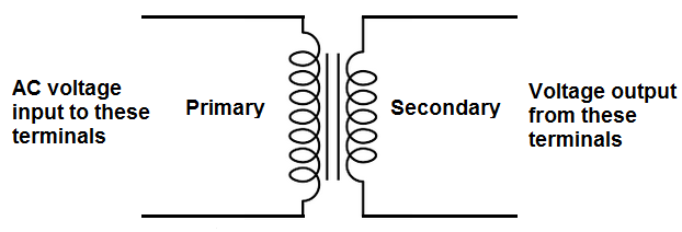
How to Build a Transformer Circuit

Equivalent Circuit of Transformer Referred to Primary and Secondary

Figure 17 from Zero sequence circuit of three-legged core type
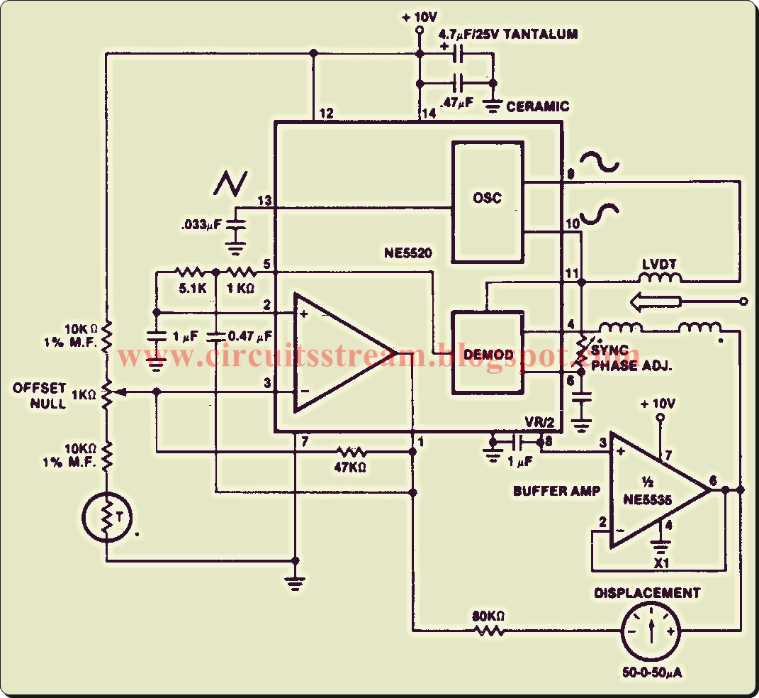
Linear Variable Differential Transformer Circuit Diagram | Electronic

Acme Control Transformer Wiring Diagram - Wiring Diagram

Equivalent Circuit of Transformer Referred to Primary and Secondary

Difference between Current Transformer and Potential Transformer
